- May 17, 2025
- Kristin Hopkins-Clegg
Are drawings just a tool for visualization?
Construction documents, often referred to as blueprints, are detailed drawings, specifications, and other written instructions that guide contractors and builders during the construction phase of a project. Many times, we get calls from homeowners asking for plans, but constructing a home, whether it be a new home, an addition, or an interior renovation of an existing home, is much more complex than drawing up simple floor plans. Homes and spaces require well-thought-out plans and 3D-dimensional detailing in order for a space to come together successfully. The modern expression “The devil is in the details” alludes to the level of detail required in the context of a design or composition. Mies Van der Rohe used this saying referring to the critical role of detailing, in the deeper appreciation and experience of a work of design or architecture. Great construction documents are clear, concise, and precise, leaving little room for interpretation.
The documents should provide comprehensive details of the project, including architectural drawings, structural plans, if required, mechanical and electrical layouts, material specifications, and construction details. Accuracy is paramount in construction documents to ensure that the information provided is correct and reflects the intended design. Missing or incomplete information can lead to errors, delays, and cost overruns during construction. They should ensure that all elements of the design work together seamlessly and comply with applicable codes and regulations. Construction documents serve as a contract between the project owner and the contractors, ensuring that the building is constructed according to the agreed-upon design and quality standards.
“Construction Documents are the blueprint of our vision, the language of our design. They not only articulate the aesthetic and functional elements but also serve as a roadmap for contractors to make it reality.”
Kristin Hopkins-Clegg
Architectural drawings are a key part of construction documents, providing detailed graphical representations of a building’s design. These drawings serve as a visual guide for builders, contractors, and other people involved in the construction process. Here are some common types of architectural drawings:
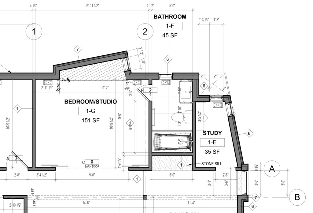
- Floor Plans: Floor plans are horizontal sections that show the layout of each floor of the building. They show the arrangement of rooms, walls, doors, windows, and other architectural features. Floor plans provide a bird’s-eye view of the building’s interior spaces and help to visualize how people will move through the space.
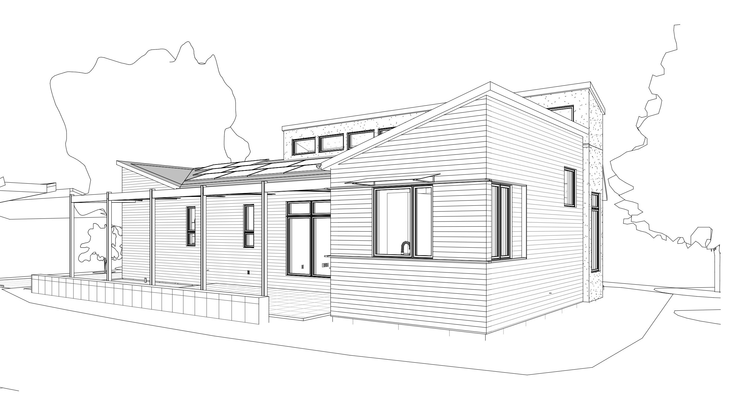
- Elevations: Elevations are vertical views of the building’s exterior walls. They show the building’s height, width, and depth, and the placement of windows, doors, and architectural details. Elevations provide a clear understanding of the building’s appearance from different perspectives.

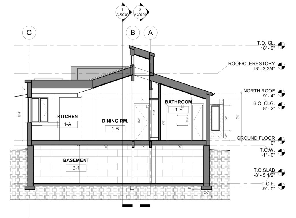
- Sections: Sections are vertical slices through the building that reveal its interior structure and spatial organization. They show details such as wall thickness, ceiling height, floor levels, and the relationship between different building elements. Sections help illustrate how the building’s various components come together in three dimensions.
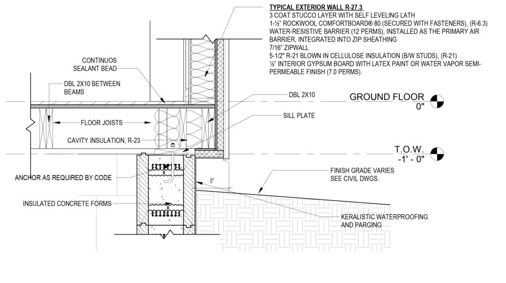
- Details: Detail drawings provide close-up views of specific building components, such as doors, windows, stairs, and structural connections. They show how these elements are constructed and assembled, including dimensions, materials, and construction methods. Details ensure that each component of the building is accurately designed and specified.
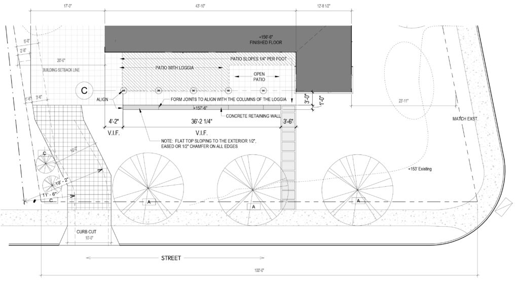
- Site Plans: Site plans depict the building’s location within its surrounding context, including property lines, neighboring structures, landscaping, and site amenities. They also show access points, parking areas, utilities, and other site features. Site plans help to integrate the building into its environment and address site-specific considerations.
- Reflected Ceiling Plans (RCP): Reflected ceiling plans show the layout of ceiling elements, such as lighting fixtures, HVAC diffusers, sprinkler heads, and ceiling-mounted equipment. They provide a comprehensive view of the ceiling design and help coordinate the placement of mechanical, electrical, and plumbing systems.

These architectural drawings, along with other construction documents such as specifications and schedules, form a comprehensive set of instructions for constructing the building according to the architect’s design intent and quality standards and the desires of the homeowner. They are essential for ensuring that the building is built correctly and meets the needs of its users.
Clear and detailed drawings facilitate a precise understanding of the project scope, allowing contractors to accurately estimate costs, plan construction sequences, and distribute resources effectively. With well-defined specifications and construction details, one can minimize errors, reduce rework, and streamline construction processes, saving time and money.